Guitar Effects
Getting it working
I have insufficient free time to assist with debugging via email. If you are having difficulties I suggest you post a query at Aron's Stompbox Forums where there are many helpful and knowledgable people who may be willing to assist you. I check in there most days and will respond if time permits.EasyVibe
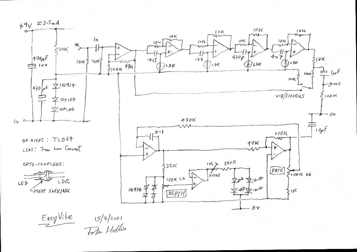
I aimed to copy the sound rather than the vintage circuit. Easy to build, low current consumption, no signal level changes on bypass, quiet and, most importantly, it does that Bridge of Sighs thing.
- Here is the schematic.
- Here is the FAQ.
- Here is a photograph of the prototype.
- Frederic Mauro has kindly contributed this PCB layout.
- There is an alternative layout using two dual op-amps at Willy´s effect pedals.
- Check out the EasyVibe at GEO for a complete package.
- You'll be needing this plus a strat and a valve amp to test it with.
Zombie Chorus
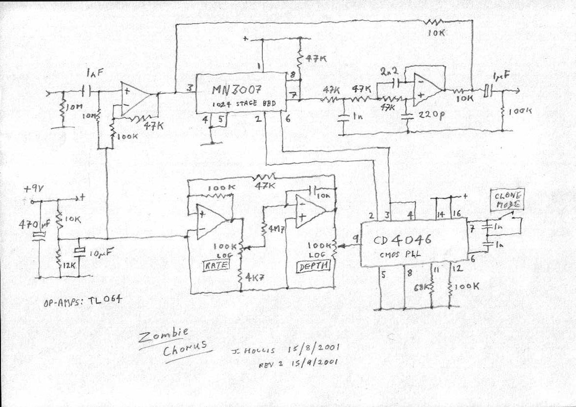
This is my reincarnation of the EH Small Clone and Roland CE-1. Unlike the Clone it has a proper depth control. It also has a switch to change between the CE-1 like 512 stage delay and the Clone's 1024 stage delay. Current consumption is very low and the circuit works down to below 6V to extend battery life. I managed to eliminate a number of the Clone's discrete components including the transistors.
- Here is the schematic.
- Frederic Mauro has kindly contributed this Rev.2 PCB layout.
- Kent Stevenson has kindly contributed this alternative PCB layout using two dual op-amps instead.
- Check out the Zombie Chorus at GEO for a complete package.
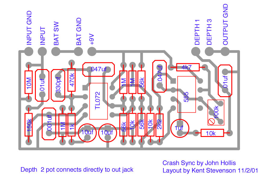
Crash Sync
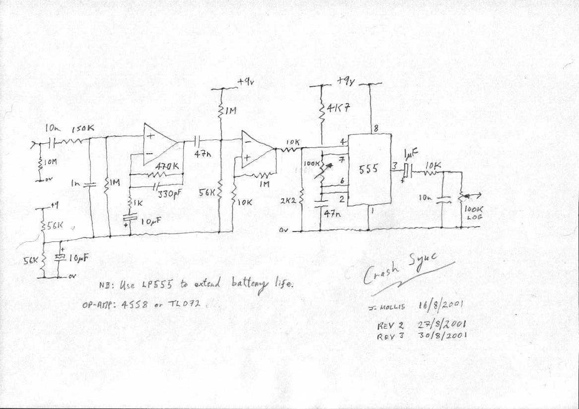
This is an oscillator sync circuit that gives the kind of effect you find on old analogue synths. Oscillator synchronisation is performed by using one oscillator to reset another. In this instance the guitar signal is used to reset an oscillator running at a higher sweepable frequency. The effect is not dissimilar to flanging. Not one for the tone freaks, this is a destroy-your-tone effect for noise vandals. The front end is copied from the MXR blue box.
- Here is the schematic.
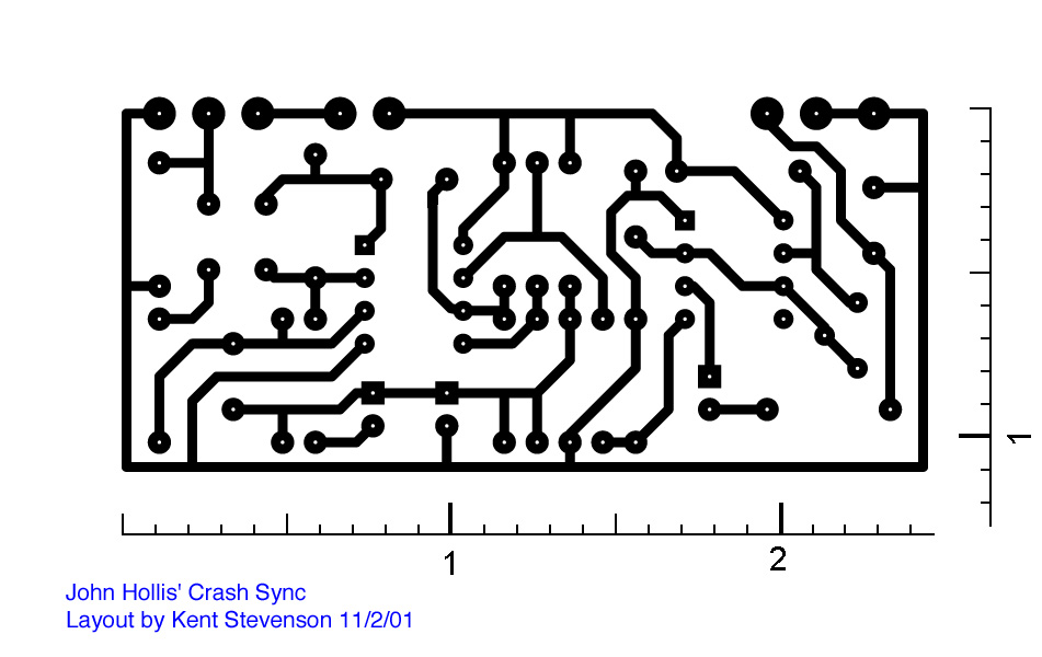
- Here is a PCB and component layout, thanks to Kent Stevenson.
- Matt Burnside kindly recorded these samples of notes and chords.
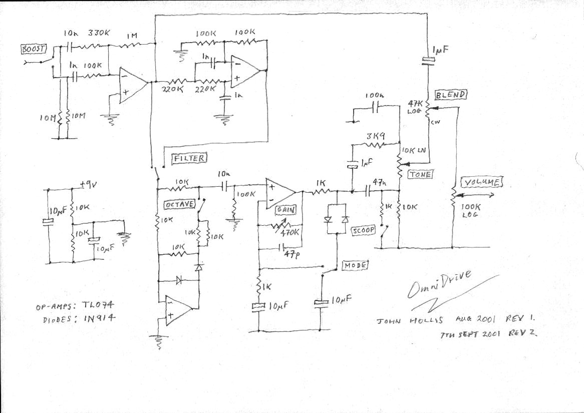
OmniDrive
This is a versatile distortion pedal. Think of it as analogue modelling, using analogue circuitry to model a wide range of analogue distortion devices. It includes the main elements found in the majority of distortion boxes. The unit comprises four sections:These stages are combined with level and tone controls to allow emulation of most of the multi-stage overdrive and fuzz units. The rotary controls are drive, tone, blend and volume. The switches are treble boost, low-pass filter, octave up and distortion mode. I have also added an optional scoop switch to the tone control circuit. This cuts the mid-range and should be popular with death metal noise vandals.
- A pre-amplifier with switchable treble boost.
- A switchable low pass filter.
- A switchable full wave rectifier for octave-up effects.
- A clipping stage with variable gain and two clipping modes.
I suggest mounting the clipping diodes via a 3.5mm miniature break jack. That way you can insert little plugs with germanium diodes or asymmetric diodes or whatever in them.
- Here is the schematic.
- Check out the OmniDrive at GEO for a complete package.
Here are some sample settings:
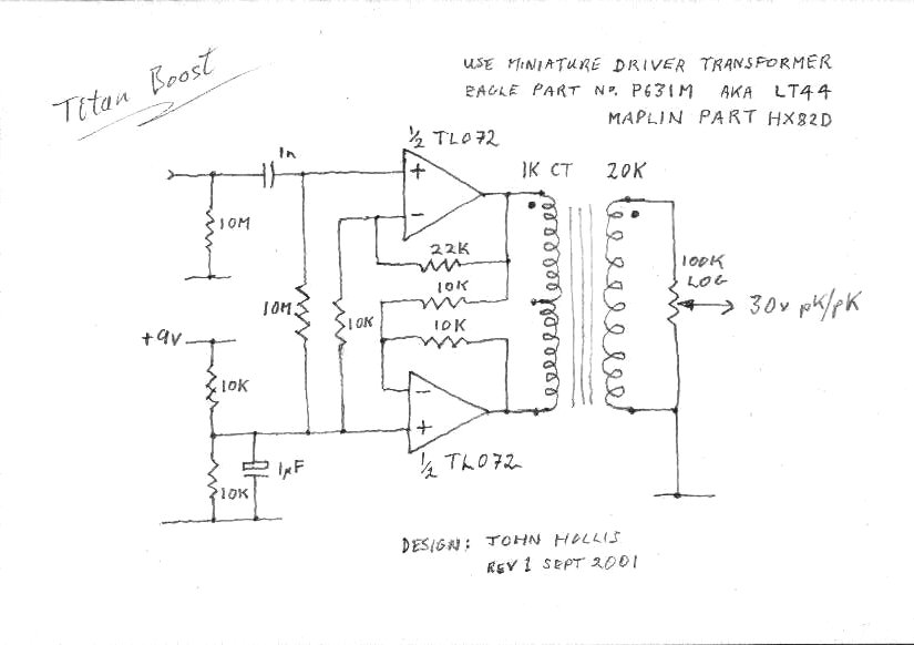
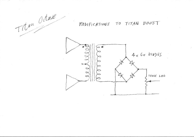
Distortion Device Boost Filter Octave Mode Drive Blend EH Big Muff Off On Off FB Max Min Fender Blender Off Off On Clip Max Blend TS-808 Off Off Off FB Low Min SRV On Off Off FB Low Blend MXR Distortion+ Off Off Off Clip 50% Min Ampeg Scrambler On Off On FB 50% Blend Octavia Off On On Clip Low Min Clean Boost Off Off Off N/A Min Max Treble Boost On Off Off N/A Min Max Titan Boost and Titan Octave
A simple boost circuit that gives 30 volts pk/pk output using a 9 volt battery. The addition of a Ge diode bridge makes a surprisingly good octave box.
- Here is the boost schematic.
- Here is the octave schematic.
- Check out GEO for the PCB layout.
The Frobnicator
This is a ring-modulator which doubles as a tremolo. It was designed as a replacement for the somewhat over-complicated ElectroHarmonix Frequency Analyzer with its ridiculous high-voltage wall-wort and huge metal box. I've got it down to a 3080 OTA and a dual op-amp.
- Here is the frobnicator schematic.
- Check out GEO for the PCB layout.
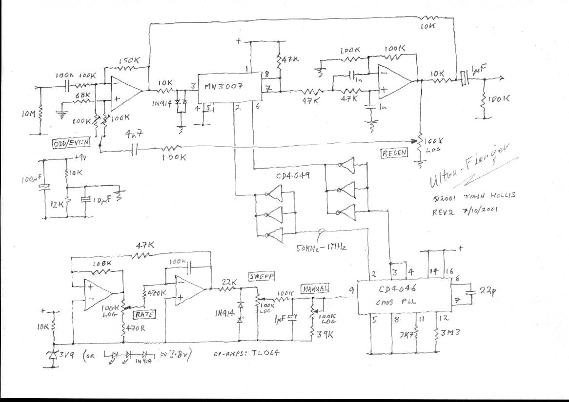
Ultra-Flanger
I was originally going to develop a minimum part count version of the EH Electric Mistress. Instead I went for a something with the versatility of an MXR flanger and the extra wide sweep that the A/DA flanger was known for. It needed an extra chip to get the wide sweep but it's worth it. Current consumption is very reasonable at around 2 to 8 milliamps dependent upon clock frequency.
- 7th April 2002: I have made a major correction to the schematic as a result of getting a second board going. The manual sweep circuit should return to ground not vref. I also increased the feedback limiting resistor from 100K to 270K. This area of the circuit might bear some experimentation as the cap in series with that resistor determines the amount of bass in the feedback signal which affects the onset point.
- Here is the new corrected ultra-flanger schematic.
- For comparison, here is the old rubbish incorrect schematic.
Rock Face
I've taken the classic Fuzz Face circuit and added optical temperature compensation. This ensures that the output stage is biased at half the supply voltage regardless of variations in the transistors, particularly those caused by temperature. Tweaks: Obviously, one could make the bias point adjustable, but it sounds fine set to halfway. One could add a resistor across the LDR to set the maximum value which would also cut current consumption slightly as the LED would go darker in response. This achieves lower minimum values too. Try 47K.
- Here is the rock face schematic.
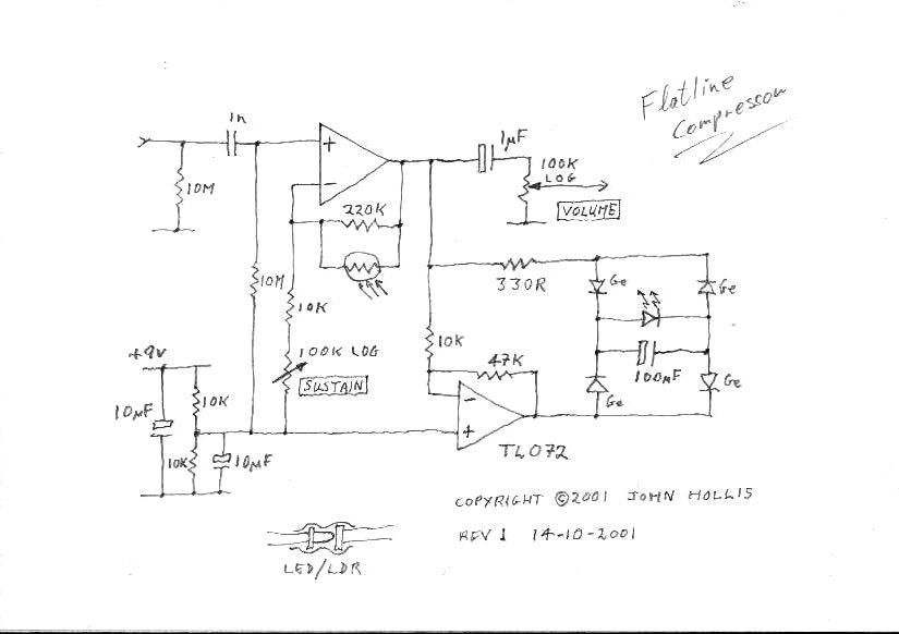
Flatline Compressor
Simple, low noise guitar conpressor.
- Here is the flatline schematic.
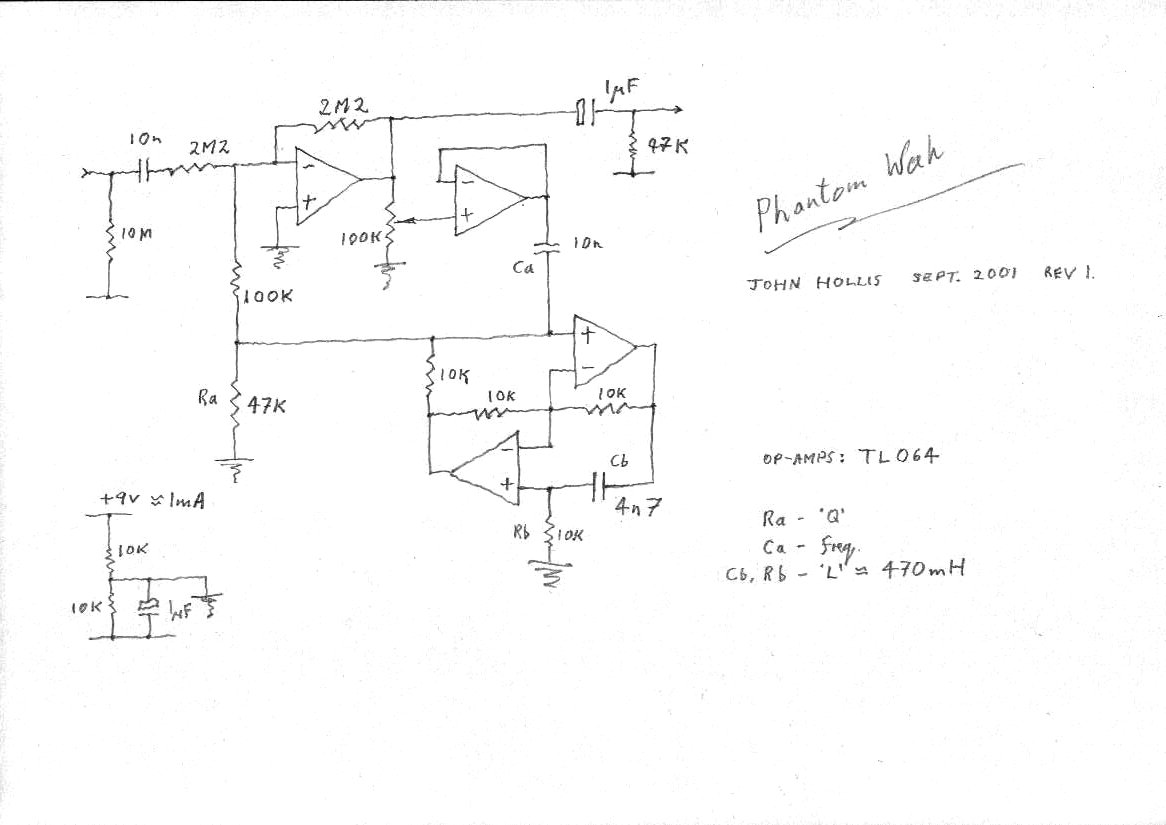
Phantom Wah - Experimental
This is an op-amp implementation of a Vox style wah, with the inductor replaced by a gyrator circuit. With the component values given the frequency response is similar to a standard wah. By replacing one of the resistors with a potentiometer the simulated inductance can be made continuously variable.
Currently this circuit has an unacceptable level of background hiss and is therefore reverted to experimental status. I will post a new version when I've got rid of the wretched noise.
- Here is the schematic.
- Thanks to R.G.Keen for the Technology of Wah pedals article.
MIDI Circuits
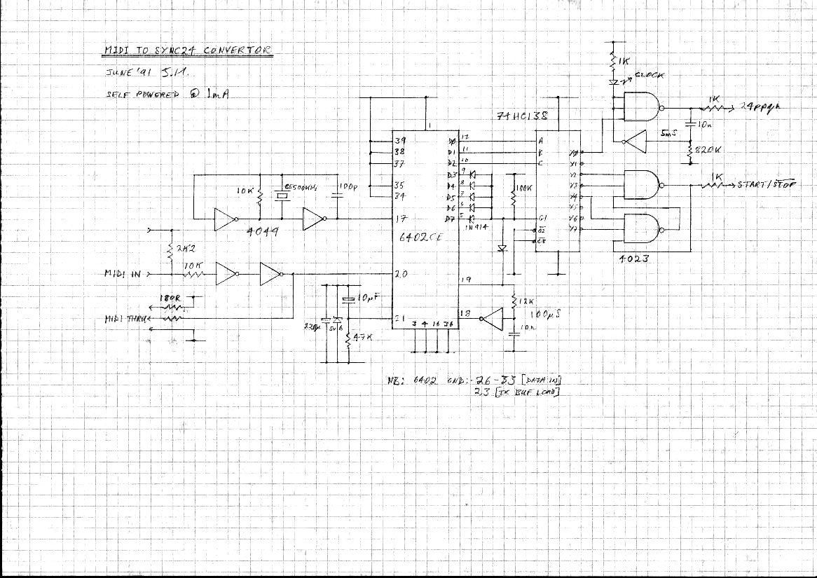
I designed these during 1991 as product prototypes. They have all been built and tested.MIDI to Sync24 Convertor
This self-powered circuit converts MIDI clocks to DIN sync24. This type of clock is used on old Roland gear and provides a 24 pulses per quarter note clock and a start/stop signal.
- Here is the MS-24 schematic.
- Here is the MS-24 PCB layout.
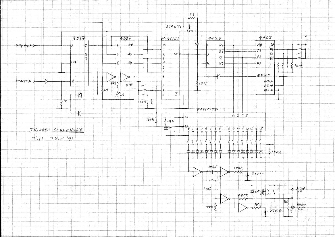
Trigger Sequencer
Add this to the above circuit to get a programmable trigger sequencer. Includes an optional audio modulation stage.
- Here is the schematic.
MIDI Program Changer
This circuit sends MIDI program changes. It's useful as a guitar pedalboard remote.
- Here is the schematic.
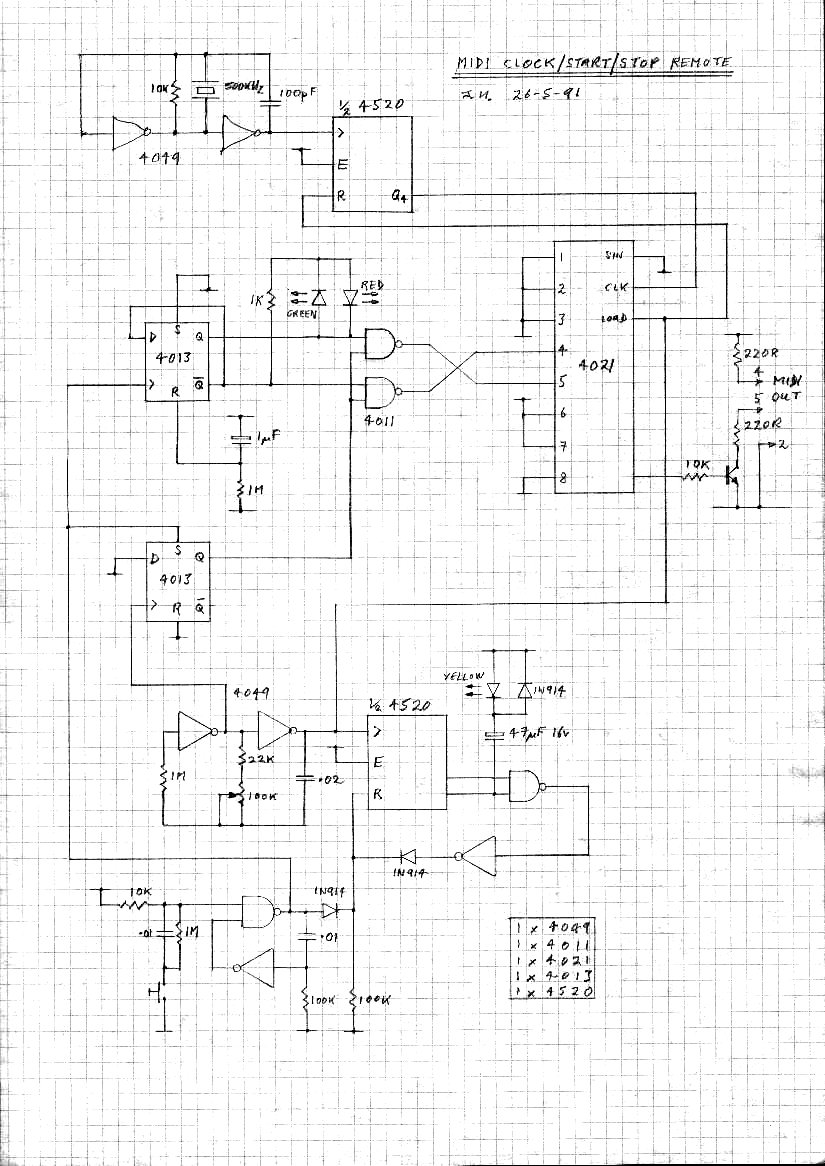
MIDI Clock
This circuit generates MIDI clocks and start/stop messages.
- Here is the schematic.
Back to John's Obsessions.Last updated: 7th april 2002
Feedback: john@hollis.co.uk
Copyright © 2001,2002 John Hollis. All Rights Reserved. These circuits are free for non-commercial use. This material may not be reproduced in any form without the prior written consent of the author. Printed publication is expressly forbidden.
Trademarks are acknowledged where used.